Coptera
The quadcopter project was conceived during my second term as a frosh. I had been constantly bookmarking quad builds for a few years, but didn't have the experience or cash to dive in. During second term, we went on a house trip, and were encouraged to build a variety of entertaining contraptions to take along. Thanks to the generosity of my friends, I was finally able to get a build rolling!
Aims
There are plenty of beautiful, high performance 'copters out there tuned for acrobatics, photography, synchronized flight, and world domination. I figured I'd have a shot at a heavy lifting configuration - something I've only seen in a couple of builds. The 'copter must be very stable, quick enough to compensate for load shifts when objects are released, and carry enough power to stay in the air for a usable amount of time.
And So it Began!
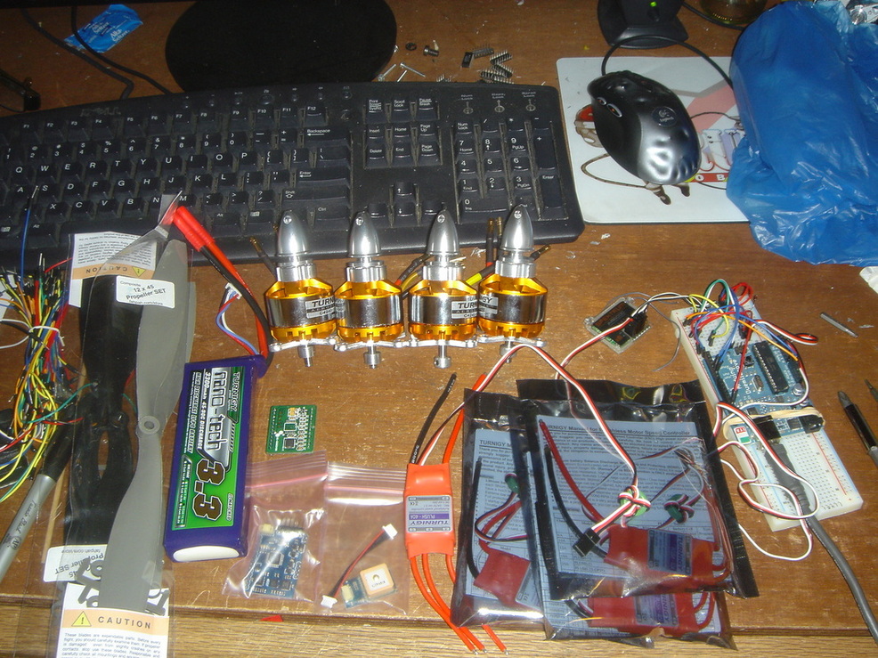
I put an order in to Hobbyking, and with a little extra for the shipping the parts arrived within a week. I laid them out on my spotlessly clean desk to get a nice snap of what I had to work with.
Parts List
The Hobby King order:
4x #TR_P40A/2165 TURNIGY Plush 40amp Speed Controller = $85.80
4x #TR4240A-1050/2100 TR 42-40A 1050kv 35A Brushless Outrunner = $75.96
1x #N3300.3S.45/11953 Turnigy nano-tech 3300mah 3S 45~90C Lipo Pack = $37.69
1x #HCB-09/11332 9x5 Propellers (Standard and Counter Rotating) (6pc) = $3.48
1x #BOX-379g/9087 Extra Length Cardboard Box and Packing 379g = $0.00
VISA / MASTERCARD (No Paypal) + $2.46
UPS Express 3 Day (USA) 2kg $43.20
Taxes: $0.00
-------------------
Total: $248.59
Propellers actually used:
4x specs: 12x4.5, the part number for the ones I have mounted is EPP1245 (ie: this one, just make sure to buy AT LEAST two sets as
each includes both right and left rotating, but you'll definitely want backups) = about $30.00
-------------------
Total: $20.00
Frame and Hardware:
At least 6 feet of 0.5" square Aluminum Stock = about $6.00
Update: Carbon fiber tubing makes up the new frame = $23.00 for 4 feet
1/8" Lexan Sheet = Scavenged
Small Zip Ties = $2.00 for a bag of 100
Double sided foam tape = $4.00 for a roll
A handful of small screws, nuts, washers, and standoffs = scavenged
-------------------
Total: $15.00
Control and Maintenance (Already had these):
Spektrum transmitter and receiver = about $200.00
LiPo charger and power supply = about $50.00
-------------------
Total: $250.00
------------------------------------------------------------------------------------------------------------------
That comes out to something on the order of $550 if you start from scratch, $300 in my case.
The Frame (V1)
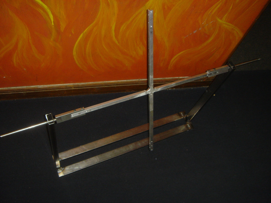
The welded frame secured on the gimball
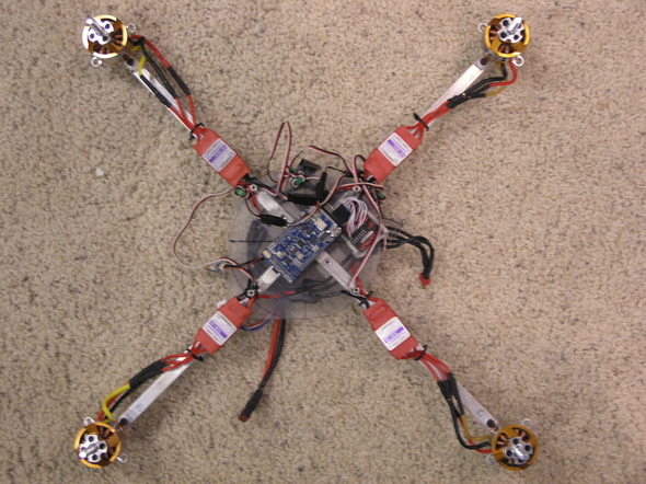
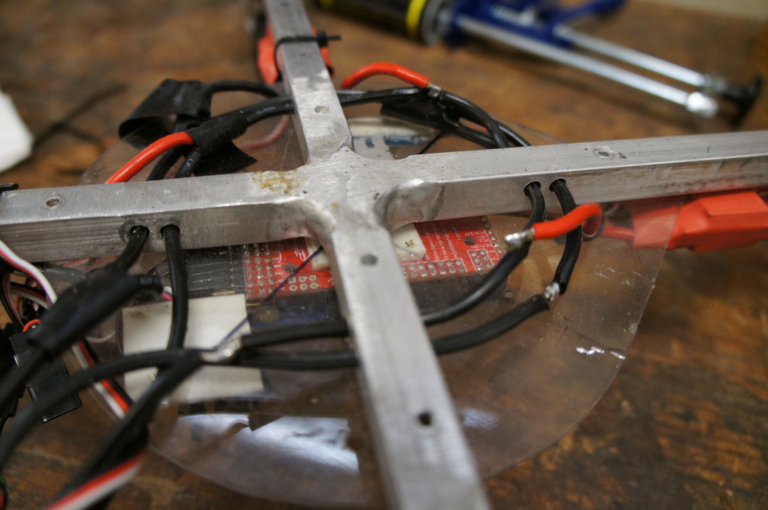
The aluminum stock was cut into one 24" and two 11.75" lengths, then joined to form a symmetric cross using a TIG welder. Find a very flat surface and make sure all the angles are square else you end up with a warped platform. I ground the joint down flush with the stock to make it easier to add mounting plates later on. The frame is really heavy (0.53kg by volume/density calculations), so I'm still looking into another material (fiberglass, carbon fiber, garolite) to replace it.
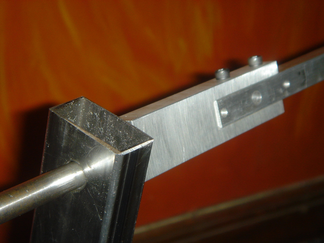
Closeup of the gimball mount arm and "bearing"
A gimball was used to secure the 'copter during testing, limiting it to either pitch or roll. The gimball frame was built with 0.75"x2.0" steel tubing. The interface mounts were machined from some stock aluminum and 0.5" steel rods. At the moment, the rods are simply inserted through a slip fit hole in the frame - not the best bearing, but it works well enough once you get used to the screech of rusted steel. I have yet to work on PID (Proportional-Integral-Derivative) tuning with it, but it does give a good general idea of correction speeds. There's a nice demo and explanation of the effects of PID here.
Electronics (V1)
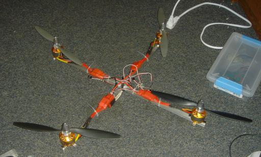
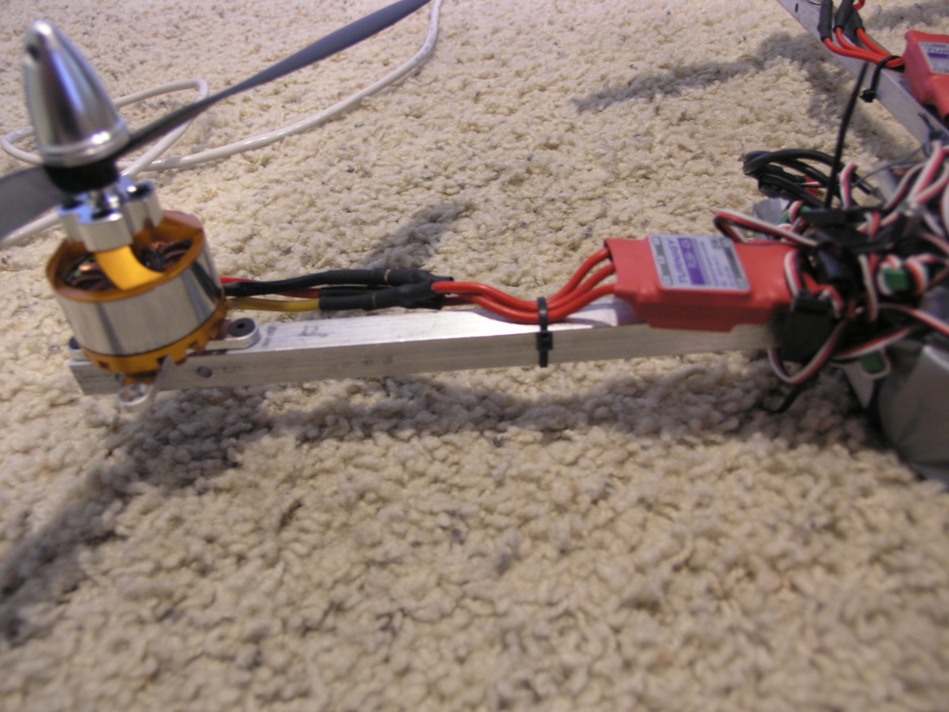
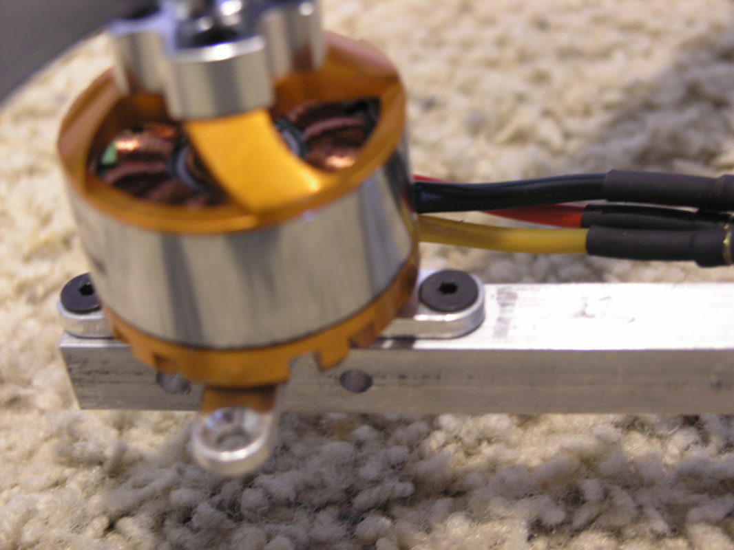
The Electronic Speed Controllers were simply zip-tied right on top of the arms. It isn't pretty or aerodynamic, but the parts are plugged together. I'm still just trying to get the thing in the air - making it pretty can wait.
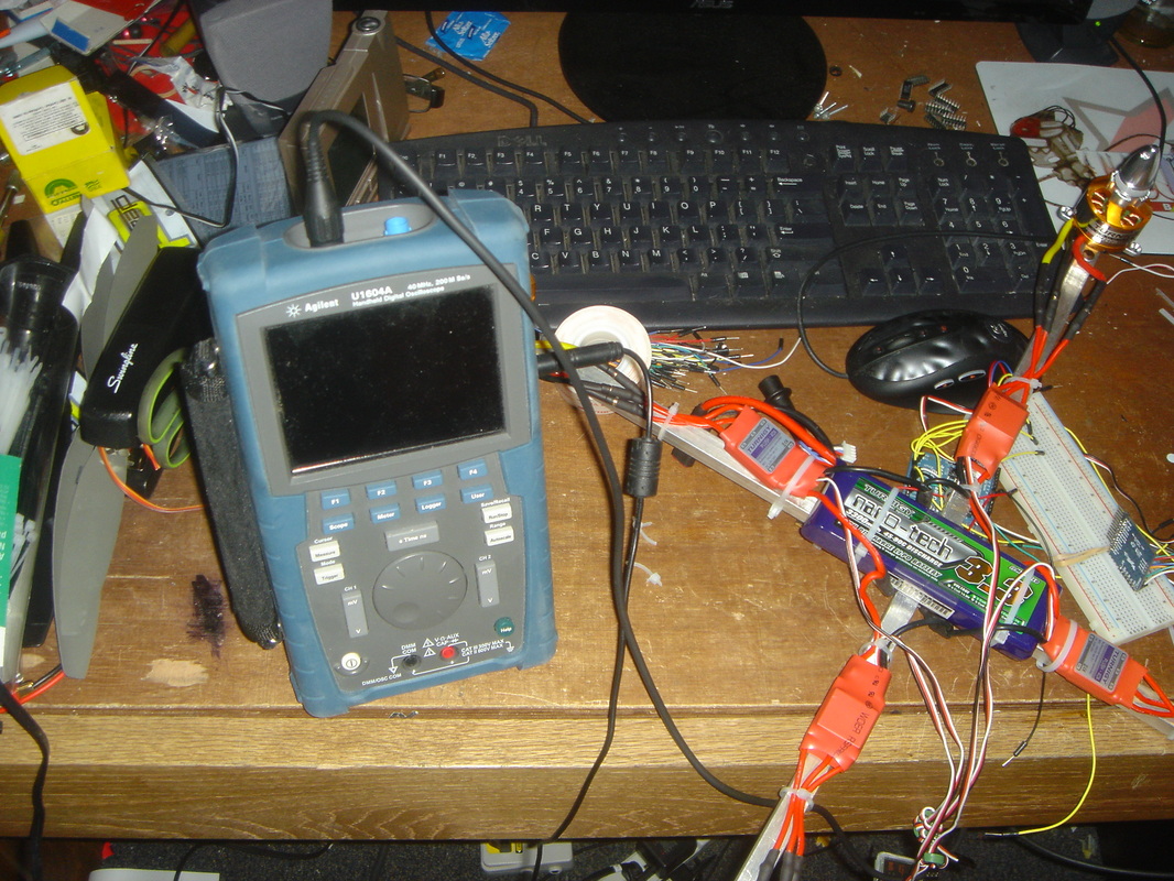
The battery is strapped onto the top of the 'copter, and the electronics will be attached with double sided foam tape to eliminate vibrations. I'm using Samson's nice handheld digital scope to try and debug a problem with PWM/PPM encoding/decoding.

This is a PWM to PPM encoder built on at Atmega168 chip. The design comes from Paparazzi, though this construction is markedly less pretty. Samson managed to work out our bug - a problem with sending the autopilot more channels than it expected, and so losing the correct timings. The orange cable running off to the left carries out the PPM signal, whereas the seven cables to the right carry PWM from the radio, power, and ground.
PWM and PPM

Digital logic can recognize two signals: HIGH and LOW. In a perfect world, these correspond to 5V and 0V (ground) for the arduino. In reality, there is a threshold above which the signal is HIGH and vice versa. To control objects like motors, servos, or fading LED's that requre more than simple on/off commands, we have to interpret patterns in the signal line. Pulse Width Modulation is a method of signal transfer based on timing and voltage. The amount of time a signal spends high in a (generic) 20 millisecond cycle can be varied to determine power in the case of a motor, or position in the case of a servo. At the end of each 20ms period the signal will fire again, so the ESC will update every 20ms, or at 50Hz. The ESC does not care explicitly about the 20ms period, but rather waits for the signal to go high, starts a timer, and stops the timer when the signal goes low again. The signal itself only lasts about 1-2ms, so why wait another 18-19ms before triggering again? Well, we could say that 20ms is about optimal to increase holding power of a servo, but we are using ESC's and motors in the quadcopter. This is where Pulse Position Modulation comes into play.
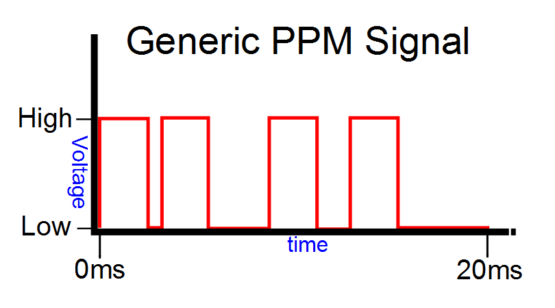
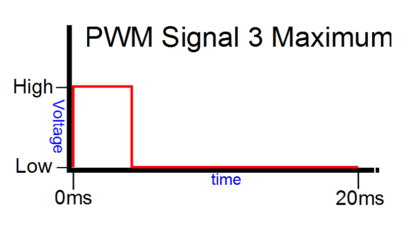
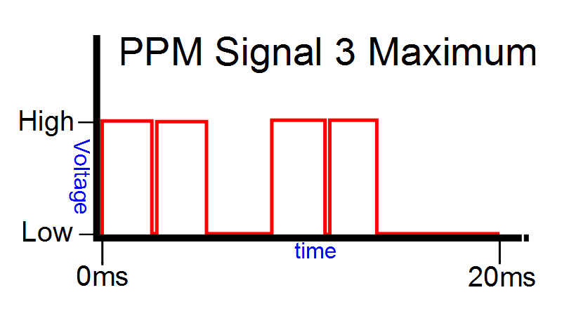
PPM allows us to string several PWM signals into the same cycle. Instead of varying the amount of time each signal spends HIGH, we vary the amount of time between each signal. If we are transmitting four signals, as to the right, we must clock in each rising edge and determine the amount of time elapsed before the next rising edge triggers. We establish an understanding between encoder and decoder that the sequence of four 1ms signals will specify channels 1-4, so the decoder can extract each channel, convert it back to PWM, and send it through the autopilot to be mixed for each ESC. A "full power" state of PWM signal 3 spending 2ms high might be interpreted from a PPM signal with signals 1 and 2 spending almost no time between each other, the third rising edge occurring 4 ms later, directly followed by the fourth rising edge. The next cycle starts 20 ms later with a repeating pattern until one of the four signals changes. There must be a minimum delay to separate the signals, but the short amount of time is designated as the equivalent of a minimum PWM pulse, say 1ms.
 |
 |
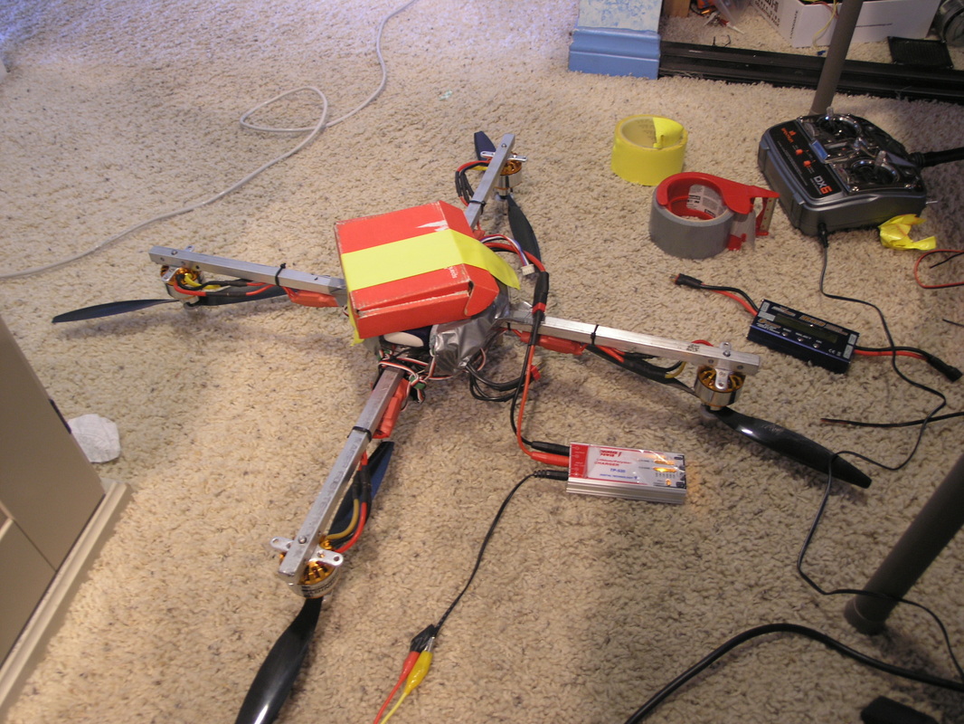
Tethered Power Test
With the PPM encoder sorted out, I could now relay all four radio signals into the Ardupilot for processing with the sensory data. Before going for a flight test entirely at the mercy of the Ardupilot's programming, I decided to affix all four arms to a table with some string.
The result was this invigorating little death machine roaring to life in the courtyard. It looks a little bit wobbly, but man, I want to get these tethers off!
Untethered Flight Test
After a few tentative revs up in my room (in Hell!), I decided to just take it outside and see what would happen. The 'copter had not yet been calibrated at all, but hey! All the more fun!
It flew - sort of. The stabilization wasn't great, I think the controls were reversed, and having never flown a quadcopter before I was not remotely used to the throttle. It was a great adrenaline rush, and Samson totally freaked out when it started to tank, but that little bit of flying just kept me motivated to keep at it and keep trying to get it right. Of course breaking a prop meant that we would have to wait another week before testing. Moral of the story? Always keep extra props handy!
Electronics (V2)
There was an interim period of a few months, during which classes and other projects gained higher priorities. Well, mostly projects. At any rate - come summer I had more time to try again. I machined new mounting plates for the electronics, routed the ESC supply between the two plates, and borrowed an Ardupilot Mega from my SURF (see AIRS). The Mega was much easier to set up than the V2 Flat, and I had the 'copter flying in no time! I no longer required the home-made PPM encoder, as the board has one built in. There are more input and output ports than I could want for, and any extra sensors hook up really easily.

Frame (V2)
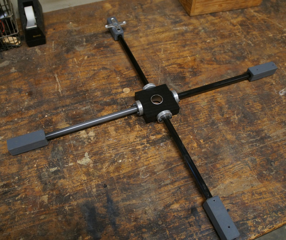
While very robust, the first frame was far too heavy. The whole 'copter came in at 2.1kg, of which the frame made up 0.8kg. After I spied a 0.500" carbon fiber tube in a hobby shop, a new frame was just around the corner.
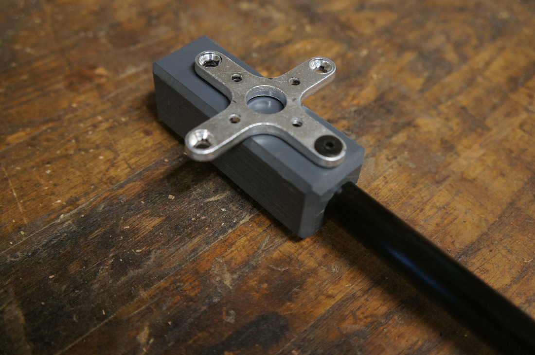
I wanted to try something unique, so I set up a system for detachable arms. As you can see in the photos below, each arm plugs into the quadcopter body and is secured with two bolts. This creates a strong mechanical connection to the arms, and a secure electrical connection for the motor wires. These wires are hidden inside the arms, so the end product will be much cleaner too.


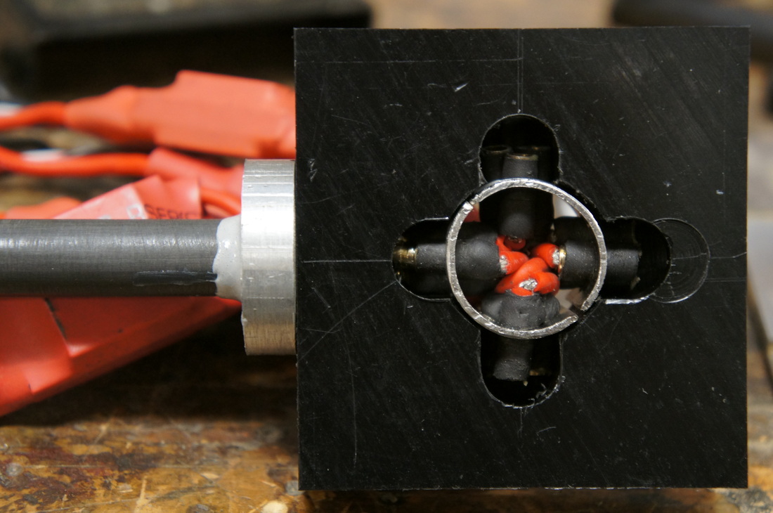
The copper wiring in the arms is unfortunately quite heavy. I may switch to using aluminum wire in the future. The carbon fiber is quite tricky to work with, as the fibers will splinter very easily. The rod cannot be clamped without making a horrible cracking sound, and should be cut with a grinding bit. My connections to the rod are all made with high strength epoxy, and all surfaces are well sanded before bonding. The central plug hub was made from a section of 1" steel tubing. I machined the piece by making guesses at where the three plug holes should be relative to a traced bounding circle. The piece easily deformed under the pressure of a drill bit, so I had to go very slowly. Even so, it is a piece better made on a 3D printer. Using plastic would also decrease the chances of an electrical short.
